Motor Patching
How to configure motor assignments and connections in the RTMC130 Motion Control System.
Motor Patching Guide
This guide explains how to configure which physical motors are controlled by which software axes in the RTMC130 system. Motor patching is essential for customizing your setup to match your specific hardware configuration.
Note: Changes to motor patching affect how the system interprets commands and can cause unexpected motion if configured incorrectly. Always verify your patches with small, controlled movements before running at high speeds.
Understanding Motor Patching
Motor patching is the process of assigning software axes (the ones you see on the Control Panel) to physical outputs on the RTMC card (which connect to your motor drivers). This allows you to:
- Customize which physical motor is controlled by which software axis
- Change the configuration without physically rewiring your system
- Create logical groupings of axes based on their function
- Compensate for hardware changes or replacements
How Patching Works
The RTMC130 system has two key components in its signal path:
- Logical Axes - The axes you see and interact with in the software interface (Axes 1-48)
- Physical Outputs - The actual electrical connections that go to motor drivers (Motors 1-48)
Patching creates a mapping between these two components. By default, Axis 1 controls Motor 1, Axis 2 controls Motor 2, and so on. However, through patching, you can create custom mappings like:
- Axis 1 controls Motor 5
- Axis 2 controls Motor 3
- Axis 5 controls Motor 1
Example Scenario: You have a legacy move file that refers to Axis 3 as "Pan", but in your new physical setup, your pan motor is connected to output 5. Rather than rewiring the system, you can patch Axis 3 to control Motor 5.
Accessing the Patch Motor Screen
There are two ways to access the motor patching interface in RTMC130:
Method 1: Using Mouse Jog
- From the main Control Panel, type
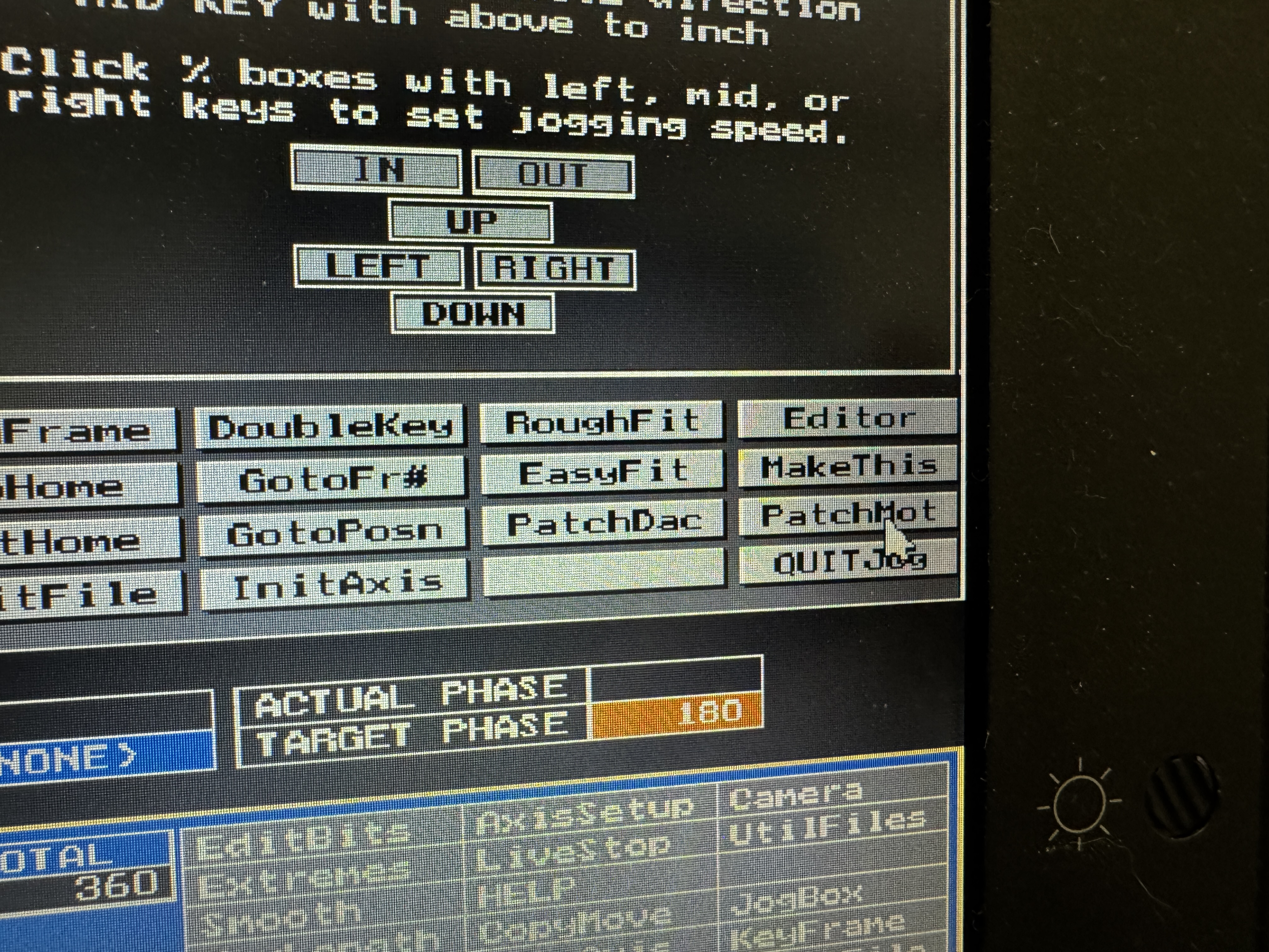
mjand pressEnterto open MouseJog - Click on the
Pat Motbutton in the MouseJog interface - The Patch Motor screen will appear
Method 2: Using Direct Command
- From the main Control Panel, type
pmand pressEnter - The Patch Motor screen will appear directly
Tip: The pm command (Patch Motor) is one of several two-letter commands in the RTMC130 system. These commands provide quick access to various functions.
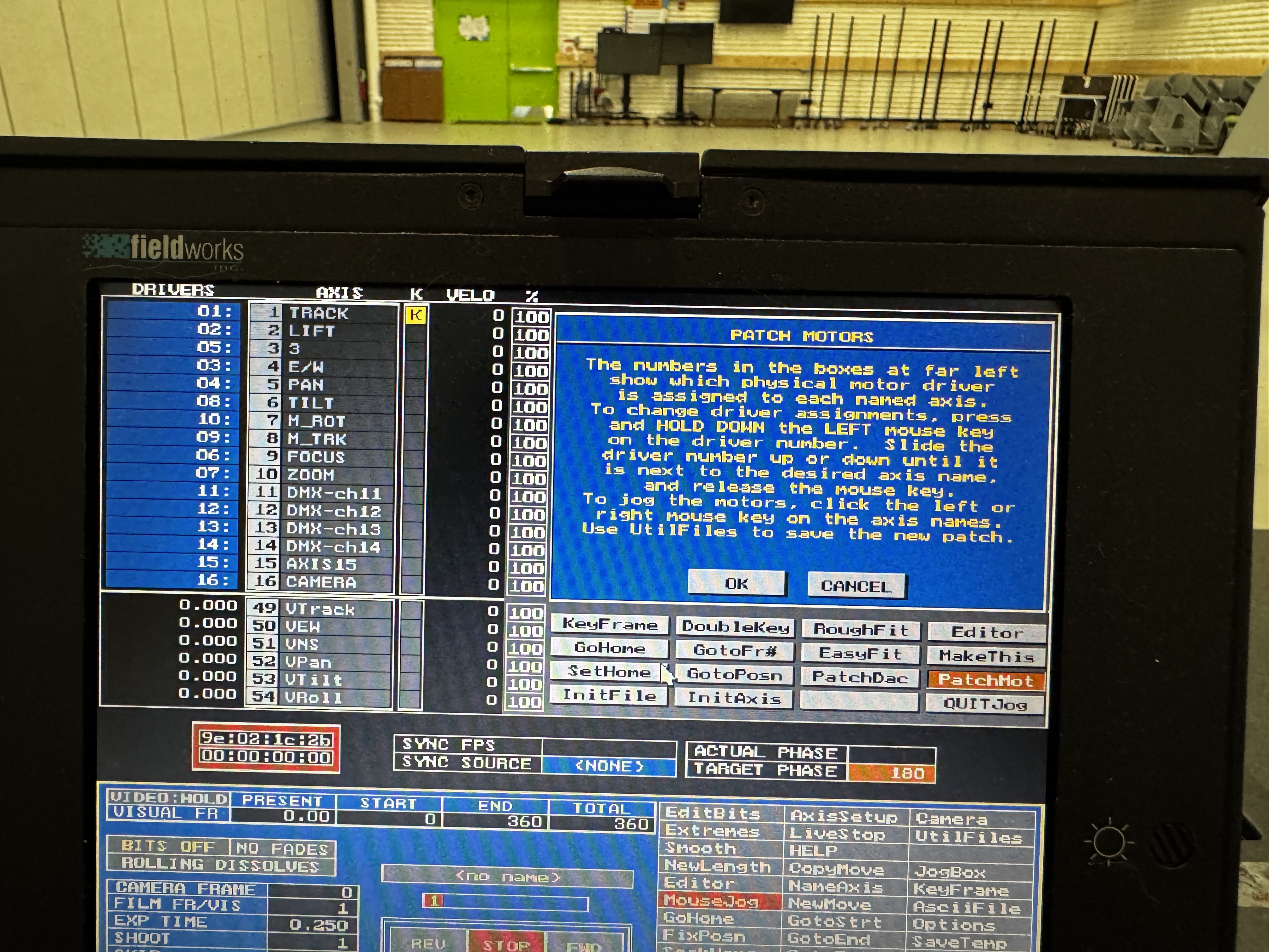
The Patch Motor Interface
Once open, the Patch Motor screen shows a table with two columns:
- Left Column: Software Axes (numbered 1-48 for RTMC48 systems)
- Right Column: Physical Motor Outputs (also numbered 1-48)
Each row shows which physical motor is controlled by each software axis. In the default configuration, the numbers match (Axis 1 controls Motor 1, etc.).
Configuring Motor Patches
To change which physical motor is controlled by a particular software axis:
Step-by-Step Motor Patching
- Access the Patch Motor screen using one of the methods described above
- Locate the axis you want to change in the left column
- Click on the corresponding motor number in the right column
- A text entry field will appear, allowing you to type a new motor number
- Enter the number of the physical motor you want this axis to control
- Press
Enterto confirm - The display will update to show the new mapping
- Repeat for any other axes you want to change
- Press
ESCor clickExitto save changes and return to the previous screen
Important: Changes to motor patching take effect immediately. Be prepared for motion if any axes are currently active.
Patching Rules and Limitations
- Valid Motor Numbers: You can only enter motor numbers that are valid for your hardware (1-16 for RTMC16, 1-48 for RTMC48)
- Multiple Assignments: You can assign the same physical motor to multiple axes, though this is rarely useful in practice
- Unassigned Axes: If you enter "0" as the motor number, that axis will not control any physical output
- Persistence: Patching assignments are saved in the system's setup file, so they will remain in effect until changed again or a different setup is loaded
Example: To make Axis 1 control the physical motor connected to output 4:
- Find Axis 1 in the left column
- Click on its current motor assignment in the right column
- Type "4" and press
Enter
Now when you jog Axis 1 or include it in a move, the system will send signals to physical output 4.
Standard Configuration
For our typical setup with the MOCO Robot, we use the following standard motor patching configuration:
| Software Axis | Physical Motor | Function |
|---|---|---|
| 1 | 1 | Track (Forward/Backward) |
| 2 | 2 | Lift (Vertical Movement) |
| 4 | 4 | East/West (Left/Right) |
| 5 | 5 | Pan (Horizontal Rotation) |
| 6 | 6 | Tilt (Vertical Rotation) |
| 7 | 7 | M_ROT (Roll Rotation) |
| 8 | 8 | M_TRM (Additional Axis) |
| 9 | 9 | Focus |
| 10 | 10 | Zoom |
Note that in this configuration, we skip physical motor 3 because of our hardware design. This is reflected in the RTMC output numbering as well, where we don't use position 3.
Note: This is the default configuration referenced throughout the documentation. If you modify this patching, remember to account for the changes when following other procedures in this guide.
Verifying Your Motor Patches
After making changes to motor patching, it's crucial to verify that each axis controls the correct physical motor. Follow these steps:
Testing Motor Patches
- Set Low Jog Speed:
- Before testing, set a slow jog speed (1.0-3.0) for each axis you've modified
- This ensures any unexpected movement will be slow and controllable
- Clear the Area:
- Make sure there are no obstructions in the movement path of any motors
- Keep hands and objects clear of moving parts
- Test One Axis at a Time:
- Select the first axis you want to test
- Gently press
+to jog in the positive direction - Visually confirm which physical motor moves
- Press
-to return to the starting position - Repeat for each modified axis
Important Safety Check: If any motor moves in an unexpected way or the wrong motor moves, immediately press STOP/CANCEL to halt all motion. Return to the Patch Motor screen and correct the patching before continuing.
Common Patching Issues
Be aware of these common issues when working with motor patching:
- Duplicate Assignments: Assigning the same physical motor to multiple axes can cause confusion during programming
- Missing Assignments: Accidentally setting an axis to motor "0" will result in no movement when that axis is commanded
- Reversed Direction: If a motor moves in the opposite direction than expected, use the AxisSetup screen to invert the axis direction rather than changing the patching
- Range Limits: After changing patching, verify that the software limits for each axis still make sense for the physical motor now being controlled
Saving Your Patching Configuration
Once you've verified your motor patching is correct:
- Click
UtilFileson the main Control Panel - Select
Save Setup - Enter a descriptive name for your setup (e.g., "MOCO_STANDARD")
- Press
Enterto save
This saves your motor patching along with other system settings so you can reload them later if needed.